
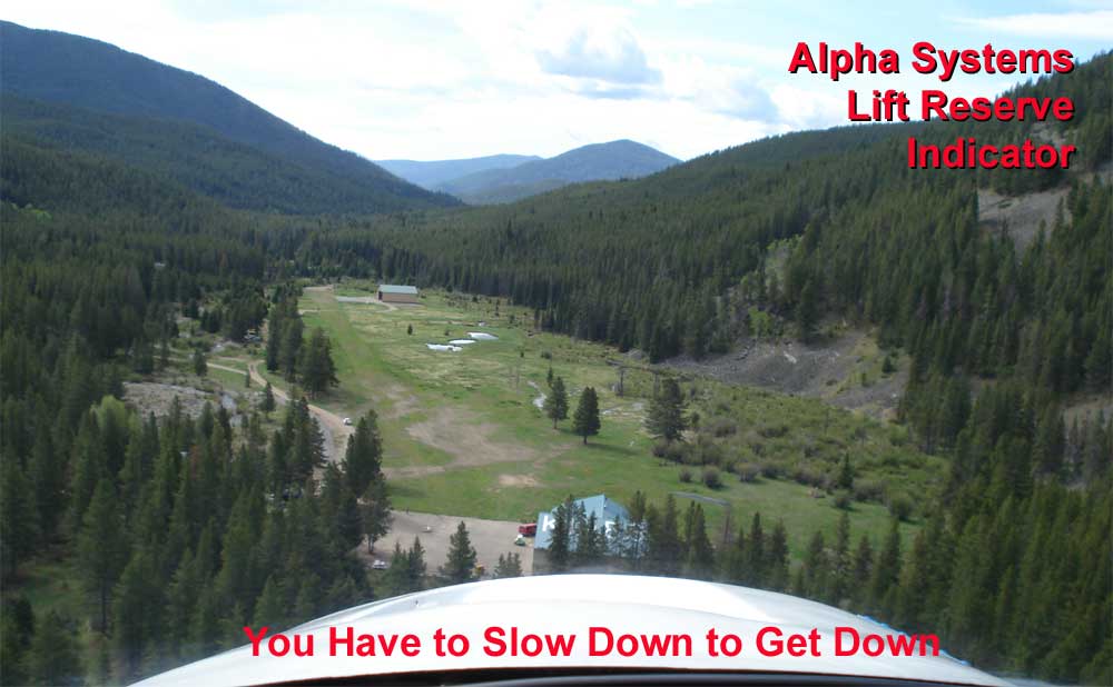
Landing at the 1,700-foot-long Klies Air Strip
(MT43) south-
west of Helena, Mont. at 6,300-foot elevation requires precision.
I fly air taxi in a Cessna 180 throughout the northwestern Rocky Mountain region, and many of my destinations are short strips at high altitudes with challenging approaches. Though I often set and maintain a given aircraft attitude for short-field approaches, cross-checked by the airspeed indicator, the true indication of how close an aircraft is to a stall is really the angle of attack. In m y previous career, I flew a Cessna Citation X for 2,000 hours and learned firsthand the value of an angle of attack (AOA) indicator. So when I received an Alpha Systems AOA for Christmas from my friend Gary McDonald, I was anxious to go out and play with this new toy.
The Citation X has a true angle-of-attack indicator developed by Leonard Greene of Safe Flight Instrument Corp. It is invaluable in providing the speed to fly under various conditions, especially in a wind shear situation. It is much better than waiting for the stick pusher activation that occurs automatically when the airplane is close to stalling. However, there is no way to justify the cost of this AOA indicator in a light single-engine airplane.
 Morgan
Gurdon Huntington developed an alternate, more economical method
that indirectly calculates the angle of attack by measuring
differential pressure at two locations. The not-quite-two-pound
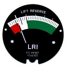
Alpha Systems AOA system indicates "lift reserve" on a gauge in the
cockpit. Since it uses a probe that is similar to a blade-type pitot
tube with a forward and aft port, it is more correctly called a
pressure-differential indicator. From my point of view, it is an
affordable angle-of-attack indicator because differential pressure
equates proportionally to angle of attack.
Morgan
Gurdon Huntington developed an alternate, more economical method
that indirectly calculates the angle of attack by measuring
differential pressure at two locations. The not-quite-two-pound
Alpha Systems AOA system indicates "lift reserve" on a gauge in the
cockpit. Since it uses a probe that is similar to a blade-type pitot
tube with a forward and aft port, it is more correctly called a
pressure-differential indicator. From my point of view, it is an
affordable angle-of-attack indicator because differential pressure
equates proportionally to angle of attack.
My 1975 Cessna 180J has been modified with the Sportsman STOL leading edge cuff and Micro Aerodynamics vortex generators. It stalls around 38 knots (45 mph) indicated airspeed when operating at light weights and around 86 mph indicated in a 60-degree bank at gross weight. Regardless of the flight condition, the wing always stalls at the same angle of attack. The short-field approach airspeed must be flown with a buffer between the stall speed and the approach speed to provide sufficient air control to flare and complete the landing. The amount of buffer is a function of pilot skill and prevailing conditions (especially gusts/turbulence). Some pilots are proficient and have that warm, fuzzy feeling when flying at 1.1 Vso, while others will fly at 1.3 Vso, which is probably okay if there is a long runway available. In any case, the buffer is really a "lift reserve," that is more important than adding "X" mph to the stall speed. If you adjust your flying to always approach at a given lift reserve, you will be able to consistently fly a short-field approach with predictable performance, eliminating the float during the flare, each and every time, regardless of the weight of the airplane, the center of gravity, the flap setting, or the density altitude. An approach during turbulent, gusty conditions will cause the indicated airspeed to jump around. Rather than watching the airspeed vary, you can see the lift reserve change, and this gives a better indication of how close to the edge you are flying.
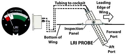
Installation
The Alpha Systems installation manual calls for four to twelve hours for the complete install. My Cessna 180 installation was completed in a little over two hours. The only time consuming part was stringing two 1/8-inch hard plastic tubes (and a 14-gauge wire for the later installation of a heading element) from the probe in the outer wing to the cockpit area.
The calibration is simple. The blade is initially adjusted to a 50-degree angle. Calibration is done in flight by transitioning to slow flight at minimum controllable airspeed until the vertical speed indicator shows "0" rate of climb or descent. The object of this exercise is to have the needle align on the mark between the red and white arcs. This determines what is called the "Zero Lift Reserve." If the needle is too far in the white, move the probe forward about one degree for each increment it is off; if it's too far in the red, move the probe aft. One or two flights should be all that you need to get the instrument calibrated.
Using the Indicator
The AOA indicator is divided into three arcs: the red arc to show danger or at least caution, the white arc for maneuvering, and the green arc that Alpha Systems calls an area with "buckets of lift."
The juncture of the red and white arcs on the Alpha Systems AOA represents the L/Dmax and is the "zero lift reserve" datum used for calibration. This provides the best angle-of-climb speed regardless of the plane's gross weight and center of gravity, the flap setting (at least on the Cessna 180), or the density altitude. It functions during banked flight or forward slips, and it is more stable than the airspeed indicator when operating in turbulence or gusty wind conditions. Flying this point after an engine failure will provide the maximum glide speed.
The red arc of the AOA is known as the "area of reverse command" or the "backside of the power curve." An unsuspecting pilot may encounter problems when operating here. If you increase the angle of attach beyond L/Dmax, you operate in the red zone and the airplane's wings are unable to generate sufficient lift to maintain level flight. An increase in angle of attack or reduction in power without lowering the nose will cause the airplane to begin to sink. Moving farther into the red arc causes the mush or burble associated with the stall, then the stall itself. The amount that the needle moves into the red zone depends on the make and model of aircraft. The Cessna wing will allow the needle to move lower in this arc before stalling than some other airplanes. Also, the application of flaps may change this indication since you are effectively changing the chord of the wing.
The white arc is the maneuvering area. Making a short-field approach to landing with the needle indicating in the lower white arc range means there will be insufficient inertia remaining to cause floating after the transition from the approach attitude to the landing attitude. This guarantees the shortest landing distance. Using the spot method for landing—that is using an aiming point on the airstrip—and maintaining an airspeed in the white arc will consistently result in a touchdown within about 50 feet of the aiming point. The juncture of the white and green arcs is where you obtain the best rate-of-climb speed, and it results in the maximum endurance glide.
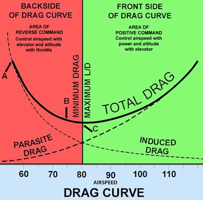 The
needle indicates in the green arc
during normal flight. A chart of the drag curve shows the total
drag is comprised of parasite drag from air friction, and induced
drag resulting from lift being produced. Induced drag varies
inversely with the square of the airspeed. If the speed is cut in
half, the induced drag quadruples. This is the opposite of the
creation of parasite drag, which varies proportionally to the square
of the airspeed.
The
needle indicates in the green arc
during normal flight. A chart of the drag curve shows the total
drag is comprised of parasite drag from air friction, and induced
drag resulting from lift being produced. Induced drag varies
inversely with the square of the airspeed. If the speed is cut in
half, the induced drag quadruples. This is the opposite of the
creation of parasite drag, which varies proportionally to the square
of the airspeed.
Suppose the pilot of a Cessna 180 on approach to an airstrip sees he is below the desired glade path. The first reaction is to pull back on the control wheel to extend the glide. When operating on the backside of the drag curve, this does not arrest the rate of descent; rather, it increases the sink.
The correct response goes against your grain; you need to lower the nose slightly and increase the power. On the "backside" of the power curve it is important to pitch to airspeed and power to altitude (or rate of descent). If power is unavailable, such as during an engine failure or flight in a sailplane, you must lower the nose to increase the airspeed and reduce the rate of descent.
Assume the pilot did not make the correct response and continues to approach the runway with the airspeed too slow and with the increased sink rate. Upon arrival at the flare point, the wing is unable to generate sufficient lift and the pilot, working with a limited amount of elevator movement, finds that when he pulls back on the control wheel, the nose does not come up and the descent is not arrested. Under this circumstance, there is not enough power available, even with full throttle, to stop the sink and make a safe landing.
Flight Test Results
The AOA provides safety. If shows the proper indications with and without flaps extended for the best angle of climb, the best rate of climb, the minimum sink speed, and the maximum endurance speed.
How does it do this? The wing flies on angle of attack, not airspeed. To confirm that the instrument really works, I flew at zero lift reserve and performed a forward slip to the left. The needle moves about three increments into the red zone. The same occurred with a slip to the right. At first I thought it might react similar to an airplane, such as a Cessna 150, that has the static vent on only one side of the fuselage. Slip toward the static vent while maintain the same glide attitude and the indicated airspeed decreased about 10 knots; slip away from the vent the the indicated airspeed increases about 10 knots. The AOA doesn't react in the same manner. It actually shows that a forward slip in either direction is effective in reducing lift resulting in an increased sink rate and indicating a lift reserve diminishing toward the red zone.
 I
was a little skeptical when I started my first approach using the
AOA, flying at zero lift reserve. Although I was at a light weight,
I was certain that I would run out of elevator control during the
flare and encounter a bounce or at least a solid arrival, due to the
low indicated airspeed on approach. It didn't happen. The airplane
touched the runway like a butterfly with sore feet and stayed firmly
on the ground. No float, no bounce. Adding 360 pounds of fuel,
mechanic's tools, survival equipment, and other gear increase the
weight about 500 pounds. The next approach at zero lift reserve
resulting in a higher indicated airspeed on approach with sufficient
elevator authority to flare without floating, and again the airplane
was solidly on the ground.
I
was a little skeptical when I started my first approach using the
AOA, flying at zero lift reserve. Although I was at a light weight,
I was certain that I would run out of elevator control during the
flare and encounter a bounce or at least a solid arrival, due to the
low indicated airspeed on approach. It didn't happen. The airplane
touched the runway like a butterfly with sore feet and stayed firmly
on the ground. No float, no bounce. Adding 360 pounds of fuel,
mechanic's tools, survival equipment, and other gear increase the
weight about 500 pounds. The next approach at zero lift reserve
resulting in a higher indicated airspeed on approach with sufficient
elevator authority to flare without floating, and again the airplane
was solidly on the ground.
There is a misconception about the FAA's recommended 1.3 Vso short-field approach speed. This speed is used for maneuvering. It is not the speed to be used for "over-the-fence" arrival. Those who have mistakenly used 1.3 Vso find they can't get the plane down on the runway. So what is the proper speed?
I would like to think that with more than 20,000 hours of flight time that I can jump into any airplane and "feel" the speed to use for a short-field landing. That doesn't happen.
Prior to having the Alpha System AOA, I would determine the minimum speed-to-fly for a short backcountry airstrip based on the current weight and c.g. by stalling the airplane. By slowly decreasing the airspeed with the power off in landing configuration until the stall, you will obtain the airspeed to which you add 10 to 15 percent for the indicated "over-the-fence" speed. It may be necessary to repeat this upon arrival at each short strip since the weight of the airplane changes with the fuel burn and that changes the stall speed.
Using the Owner's Manual or Pilots Operating Handbook to determine the exact approach speed for the short-field landing doesn't seem to work. Aircraft manufacturers, because of the real possibility of litigation, pad the numbers to prevent a pilot from getting too slow. I guess they don't realize that this conceivably lead to litigation "in the reverse" since the airplane may float during the landing and at a one-way strip the only option available is to run off the runway.
Probably for the inexperienced pilot the AOA indication should be mid-way in the white arc when conducting a short-field landing. With experience the approach may be flown at the bottom of the white arc, but be prepared to add power during the flare to make the elevator more effective.
The AOA is valuable during short-field takeoffs as well. Just before the needle rises toward the zero lift reserve (junction of the red and white arcs), rotate the airplane. As soon as the needle indicates zero lift reserve, climb. This is the best angle-of-climb speed for whatever configuration of weight, center of gravity, flaps and density that may exist.
Is It Worth It?
The Alpha Systems AOA is a pretty nifty gadget. It just sits there and does its job. No electrical power is required (except for the electronic display units or the optional probe heat). It allow you to approach at the minimum speed for backcountry operations without getting into trouble, and without putting into force your background, education, knowledge, training, experience, exceptional piloting skills, and the often elusive "seat-of-the-pants" feel for your airplane. A mere glace at the instrument confirms immediately that you are extracting the maximum performance from the airplane, whether it be takeoff, maneuvering, or landing.
General aviation accidents remain in about the same proportion statistically for each phase of flight year after year. The majority of accidents occur during the takeoff or landing phase of flight, followed closely by maneuvering flight. An angle-of-attack indicator may go a long way in preventing these types of accidents. Airlines and corporate aircraft have had the angle-of-attack indicator available for years. Now general aviation has an affordable indicator.
So what does the Alpha Systems AOA do? Everything an angle-of-attack indicator will do ... at a fraction of the cost.
Where can you find this amazing gizmo and what will it cost? Check it out at www.alphasystemsaoa.com
|
|
|